
Batteryless E-Paper Displays and Energy Harvesting Methods

As technology advances, various energy harvesting methods have emerged, leading to a new era of batteryless sensors. The batteryless E-paper display proposed here is one such design. (Electronic paper, also known as electronic ink (e-ink) or intelligent paper, is a display device that mimics the appearance of ordinary ink on paper.)
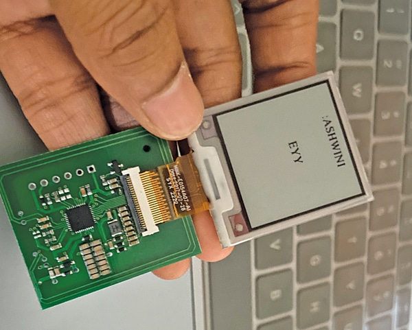
It might be surprising, but it is no longer considered rocket science or science fiction. Fig. 1 showcases the prototype of a batteryless e-paper display.
Many of you may have already seen or used batteryless e-ink displays (E-paper displays).
Also Check: E-paper Clock
Several companies are already selling them, a few of which can be checked here:

1. https://www.waveshare.com/wiki/7.5inch_NFC-Powered_e-Paper
2. https://www.ynvisible.com/news-inspiration/ynvisible-e-paper-displays-nfc-energy-harvesting
3. https://www.good-display.com/product/423.html

4. https://lummico.com/product/smarttag-batteryless-2-90
5. https://www.usocard.com/case-detail/id-32.html
6. https://github.com/GDSID/Hipoink
e-ink Display
e-ink displays are a unique kind of display where once you update the screen, the displayed content remains even if you remove the power. Power is only needed when updating, and the required amount is minimal, which can be easily supplied by harvesting RF, solar, and various other forms of energy in the vicinity.
Also Read: What Is E-Paper Display? Advantages and Disadvantages
Most batteryless displays on the market today utilize near-field communication (NFC). They operate by harvesting energy from NFC. To update the details on the display, one can simply use a phone with NFC or an NFC display writer device. The updated screen remains visible even when the display is not powered.
Such displays are incredibly useful for batteryless sensor nodes, low-power wearable devices, price tags in clothing stores and market stalls, and marketing display screens. They can also serve as smart business cards and ID cards, allowing for updates whenever necessary.
There are numerous applications for these batteryless smart displays. Here, two versions of batteryless displays have been designed.
The first version explains how NFC-based battery displays can be designed.
The second version caters to those without access to PCB SMD soldering and manufacturing processes. This version describes a Wi-Fi-based batteryless display that uses a wireless coil for power during display updates. Here only the NFC-based batteryless display and Wi-Fi-based batteryless display will be delved into.
NFC-based Batteryless E-paper Display
If one wishes to create batteryless display identity cards, business cards, or tags without extensive SMT assembly, a modular-based design approach can be opted for. An NFC energy harvesting-based display driver module compatible with e-ink displays can be purchased. To embark on the NFC-based batteryless display, the components listed in Table 1 would be required.
| Table 1: Bill of materials for NFC-based batteryless display | ||
| Component | Description | Quantity |
| DENFC-M0 energy harvesting board | SPI module DENFC-M01 | 1 |
| GDEY0213B74 e-ink display | 1.5s, partial refresh, 4 Grayscale, IC SSD1680Z, resolution 250×122 | 1 |
| ST link emulator | Connector module | 1 |
However, if one prefers designing their own with PCB and SMT assembly, a reference design is available (https://github.com/GDSID/Hipoink).
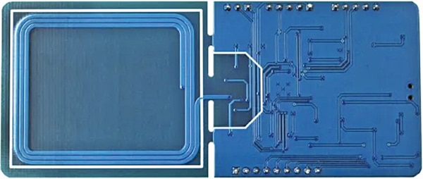
For such a prototype (NFC-based batteryless display tag), the “DENFC-M0 Energy Harvesting” display driver and the GDEY0213B74 e-ink display have been utilized. Fig. 2 illustrates the energy harvesting display driver module.
PS: In addition to the components listed in Table 1, an Android phone and an app are also required to update the display wirelessly without using a battery. The app and all other technical details can be obtained (https://buy-lcd.com/products/e-paper-display-spi-module-denfc-m01-nfc-eink-display-board).
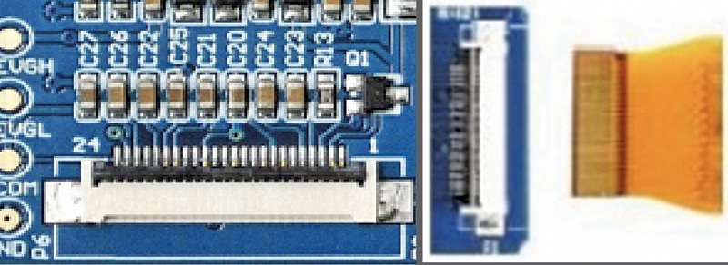
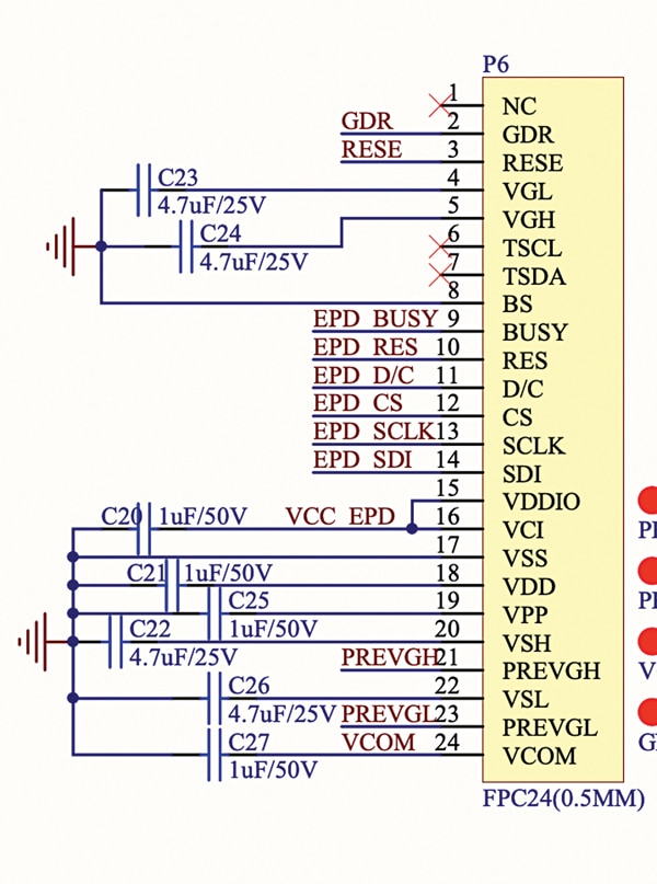
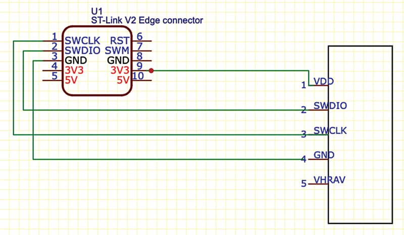
Before connecting the components, refer to Figs. 3, 4, and 5. First, connect the NFC energy harvesting GDEY0213B74 e-ink display driver module using the FPC connector provided on the DENFC-M0 energy harvesting board. Now, connect the ST emulator to the NFC display driver board. Fig. 3 shows the FPC connector and connection with the display. Internally, the display pin connections are shown in Fig. 4, while Fig. 5 displays the connection with the ST link emulator.
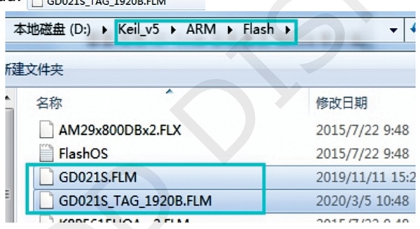
The firmware can be uploaded to the driver module using Keil. The board supports SWD download mode. Download the Keil and firmware, and then place them in the root catalogue of the Keil software. Select the MCU as ARMCM0. Now, compile the firmware and upload it to the board. Fig. 6 displays a screenshot of the Keil firmware.
For testing, download the app provided with the driver module’s QR code and install it on your phone. Place the NFC display driver on the NFC side of your phone and upload the desired image or text. After a few seconds, the display will refresh and show the updated screen with the text and image you just uploaded. Fig. 7 illustrates an Android phone displaying the e-ink display.
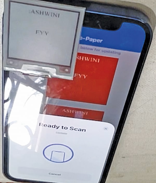
Interestingly, there is no battery connected to the display driver, yet the entire display updates without any power source, making it batteryless. The NFC driver can be removed from the phone, and the display will remain the same even without power.
Additionally, the display can be detached from the driver module and placed wherever necessary, such as on an ID card, shop price list, or advertisement display; it will remain functional for years without needing any power.
Wi-Fi-based Batteryless Display
To design a long-range wireless updatable and batteryless display, the Indusboard and a wireless powering coil can be used. As mentioned earlier, e-ink displays require only a small amount of power when updating, and the displayed screens remain unaltered even when power is removed.
Therefore, the same concept as the earlier design is employed, but instead of NFC coil energy harvesting, energy is harvested from the magnetic flux using the coil. The Indusboard, wireless power transfer coil, wireless charger module, and an e-ink display are utilized.
Whenever you want to update the display, simply place it on any wireless charger or charging module. The board receives power by harvesting the energy emitted from the charger’s coil, and the display provides Wi-Fi connectivity.
The display can then be connected to a smartphone or laptop to send the desired text or image to be shown on the screen. Once the screen is updated, it can be removed from the coil.
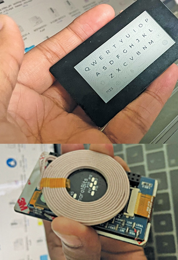
To embark on the Wi-Fi-based batteryless display, the components listed in Table 2 are required. Fig. 8 illustrates the wireless energy harvesting coil with the e-link display.
| Table 2: Bill of materials for Wi-Fi-based batteryless display | ||
| Component | Description | Quantity |
| Indusboard coin (MOD1) | Coin sized board | 1 |
| Wireless energy harvesting coil (C1) | XKT-L10 20mm20uH coil | 1 |
| E-Ink display (MOD2) | 2.13-inch SPI E-Ink display | 1 |
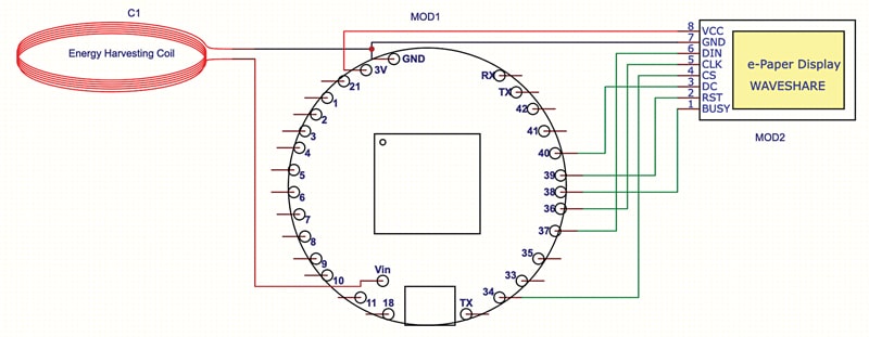
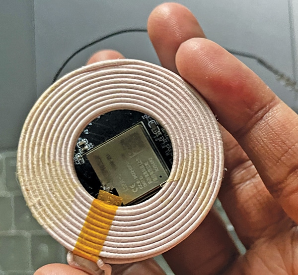
Fig. 9 shows how to connect the energy harvesting coil, Indusboard coin (MOD1), and E-paper display (MOD2). Connect the harvesting coil to the Indusboard 5V and GND pins. As the board has a wide range of voltage regulators, it converts the 3V to 9V harvested energy into regulated 3.3V, which is needed by the board and is displayed internally.
Now, connect the e-ink display SPI pins with the board SPI pins. Hardware SPI pins are used here, and the same should be defined in the code. However, other SPI pins can be changed and defined in the code as the board has flexible SPI; any GPIO can be used.
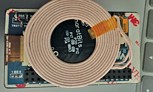
Fig. 10 displays the energy harvesting coil with the Indusboard, and Fig. 11 displays the energy harvesting coil with the e-ink display.
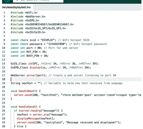
In the source code, define the SPI pins as per connections, set the display hotspot name and password, and then upload the code to the Indusboard by selecting the right board and port in the Arduino IDE. Fig. 12 shows a screenshot of the source code.
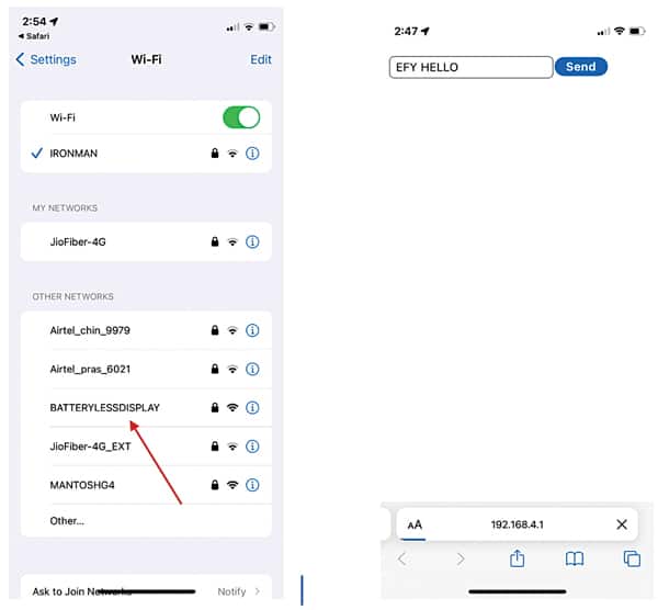
To update the display, place the display on any wireless charger or powering coil and then open the phone. Connect the phone with the displayed hotspot; here, its name is “BATERYLESSDISPLAY,” as shown in Fig. 13. Now, insert the password; by default, the password is 1234567890. Search the IP address in the web browser and send the text to display. Within seconds, the display will get updated from the harvesting coil, and the display will be ready with the new screen.
Ashwini Kumar Sinha is a tech journalist at EFY, with hands-on expertise in electronics DIY. He is passionate about AI, IoT, and electronics. He holds two design contest records and is a times winner of the US-China Makers Award.